
HOW TO CALCULATE PEDAL RATIO FOR YOUR HYDRAULIC LINKAGE.
So you want to change your clutch linkage over from mechanical or cable linkage to hydraulic linkage, why? Because you want a softer clutch pedal! Well, it doesn’t quite work that way. Your pedal pressure is a mathematical equation based on your clutch pressure at the tip of the lever, divided by your clutch linkage ratio. It doesn’t matter what type of linkage you have. So if the pressure to depress the levers of your clutch is 500 pounds and your overall linkage is 12:1, then your pedal pressure will be 41.66 lbs at the pedal pad. It can’t be any less than 41.66lbs, but it can be more, if there is added external resistance from something such as cable rubbing through it’s casing or worn out mechanical linkage.
The biggest mistake we see, when designing the hydraulic linkage, is to try and reuse the original clutch mechanical linkage attachment point. That doesn’t work and we’ll explain why. With mechanical linkage, your pedal ratio is usually 3:1, and your bell crank or Z bar ratio is usually about 2:1 and your clutch fork ratio is normally about 2:1, then you would have (3:1 pedal X 2:1 Z bar X 2:1 Fork) = 12:1. Now when you connect your master cylinder to the same 3:1 stock hole in your pedal, and you then eliminate the bell crank and the Fork, and if your master cylinder to Slave cylinder ratio is 2:1, then your overall linkage ratio would be 3:1X2:1 = 6:1. You can now see that your hydraulic linkage would be ½ of your original linkage of 12:1 .So using that same 500 lbs clutch, the original pedal pressure was 500lbs / 12:1 = 41.66 lbs, then your new hydraulic pedal pressure would be 500lbs / 6:1 = 83.33 lbs or 6:1 VS 12:1. What you’ll need to do now is, make your pedal ratio be 6:1, so that your overall hydraulic linkage ratio would be 12:1 (6:1pedal X 2:1 slave).
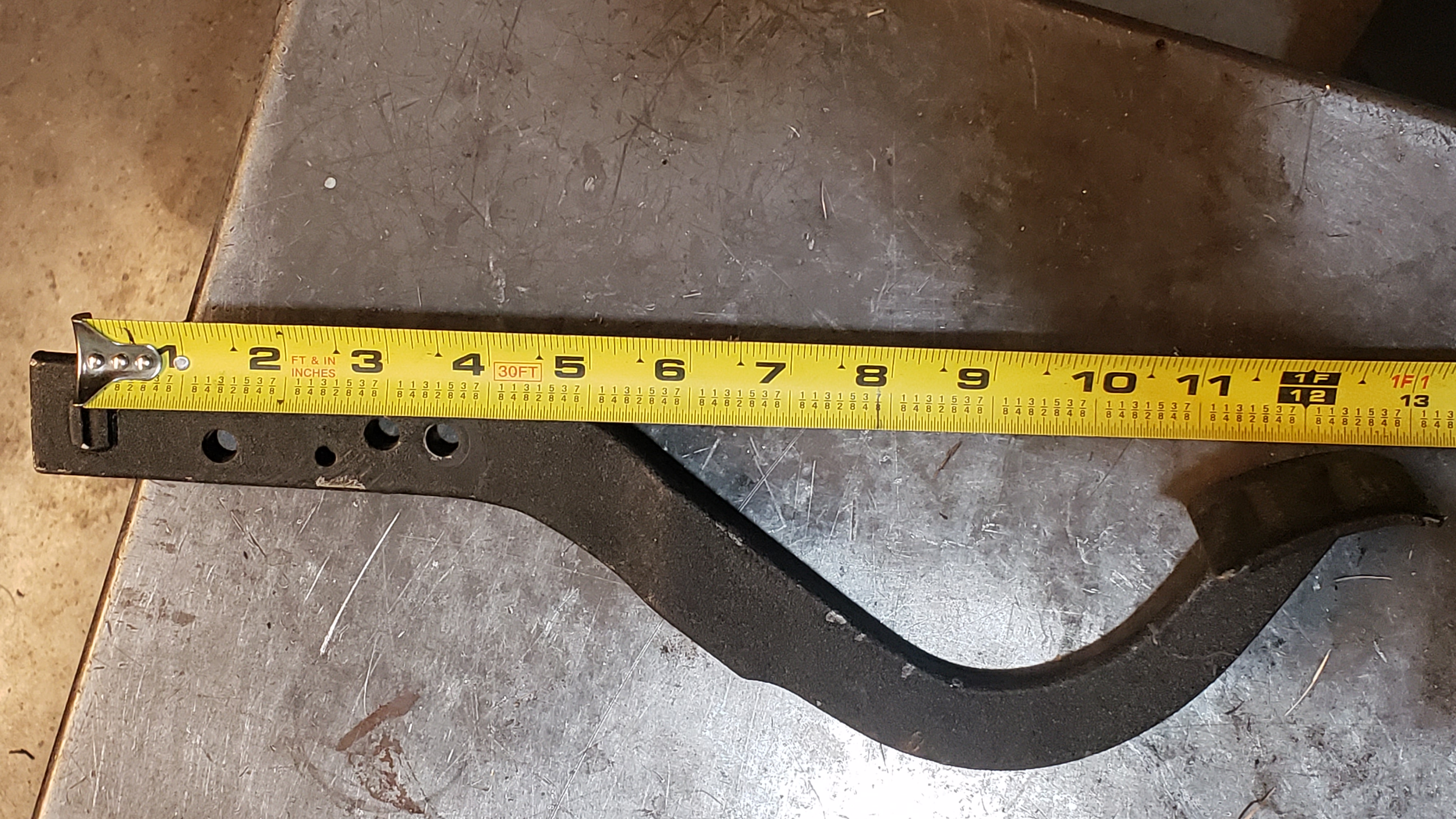
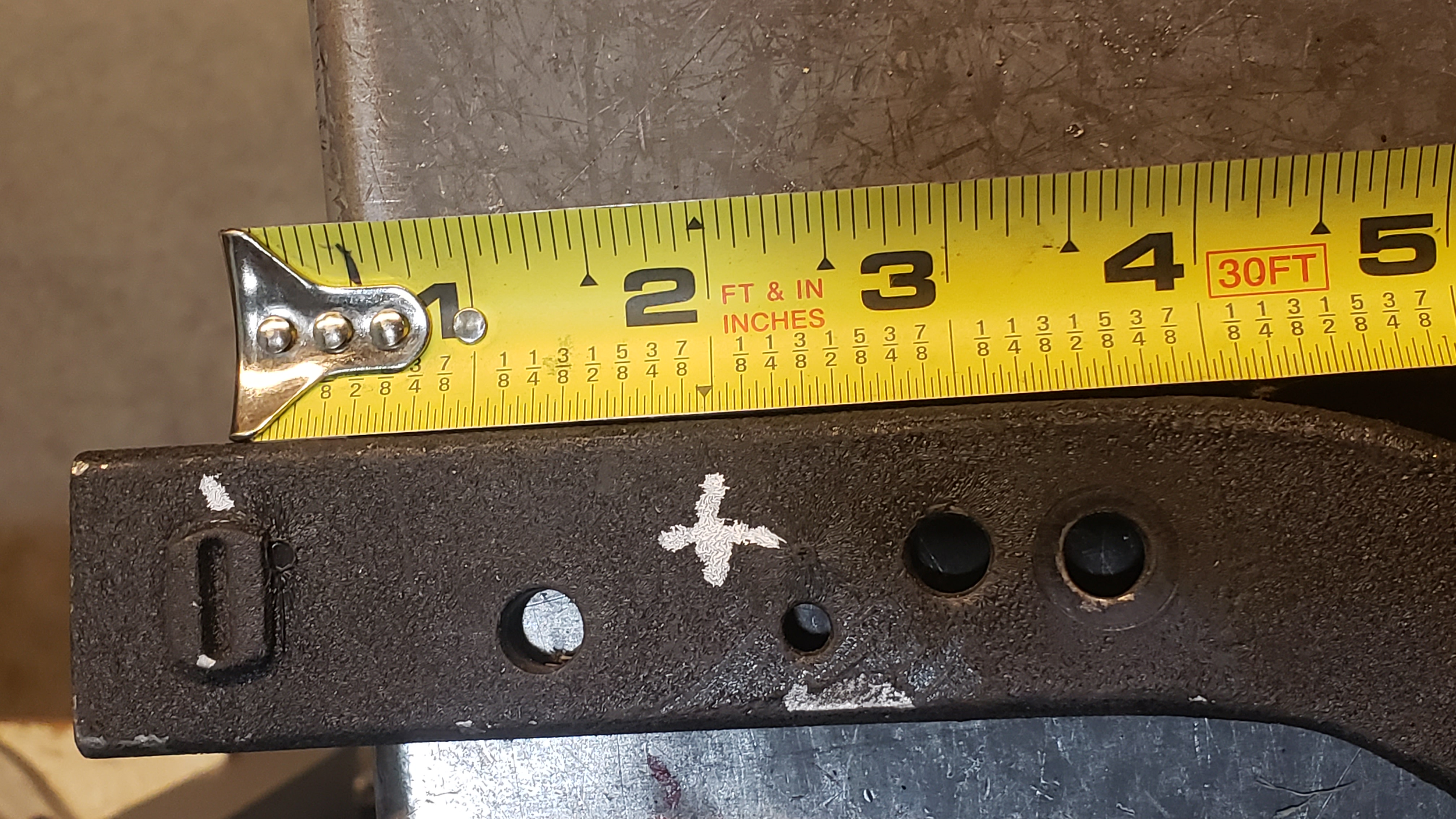
To calculate your pedal ratio you must start by measuring the length of your pedal from the center of the (fulcrum/pivot), to the center of the pedal pad at the bottom of the pedal, as shown in the picture to the left. If it measure 12” from center to center, and you want a 6:1 pedal ratio, you divide 12” by 6 and you’ll get 2”. Go back up to the (fulcrum/pivot) and come down 2” and you will have your 6:1 pedal ratio.
So you think you’re done, not yet. Now you need to figure out the geometry. As you can see from the picture below, I drew a 2” red circle to represent the radius around the Pivot point.
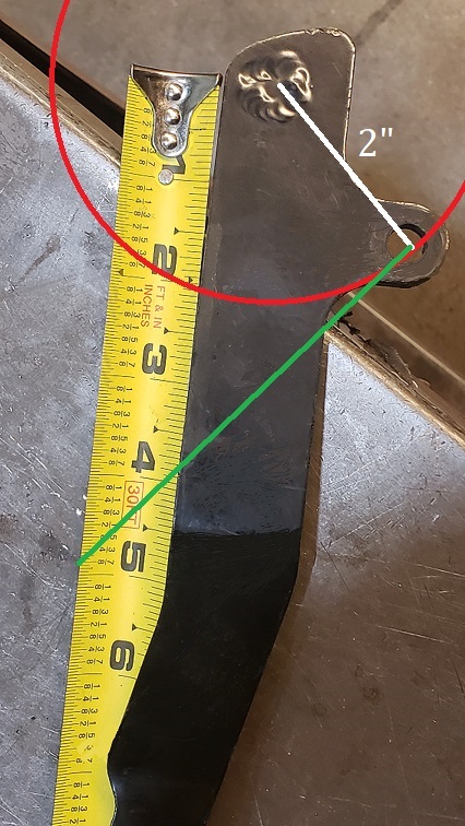
Anywhere on that red circle, is a 6:1 ratio, as compared to the length of the pedal, but we needed to push in the direction of the master cylinder with the least amount of rise or fall of the push rod as possible.
The ideal angle is a 90 degree right angle when the pedal is ½ way through its travel from the top to the bottom of the throw as measured from the fulcrum to point where the master cylinder push rod is attached to the pedal, on down to master cylinder. Now when the pedal is all the way up, it’s the same amount of degrees above right angle as it is below right angle when the pedal is down to the floor. As you can see from the picture, where the green line and white line form a right angle on the red circle, it is nowhere on the pedal. So if you notice an ear had to be added to the pedal to attach the master cylinder push rod to the correct position to give the 6:1 ratio AND keep the right angle at ½ travel. The ear was needed because the master cylinder was mounted low on the firewall to clear the brake booster and the push rod was at a steep angle. So there you have it for calculating the correct ratio and geometry. How you should have a nice soft and smooth clutch pedal with good release.
.png)
Photo: Courtesy of the Clutch & Flywheel handbook by Tom Monroe.
